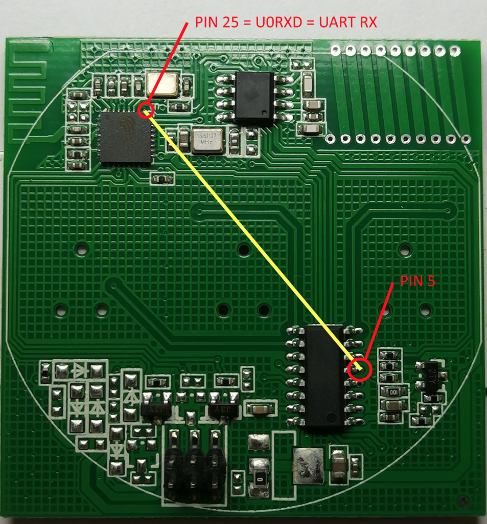
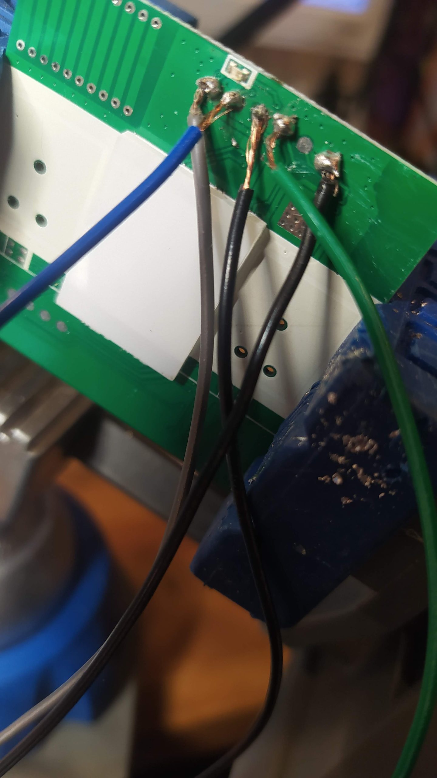
https://tasmota.github.io/docs/devices/TYWE3S/
https://templates.blakadder.com/Moes_WHT-HY609.html


https://github.com/blakadder/templates/blob/master/_templates/Moes_WHT-HY609
https://tasmota.github.io/docs/TuyaMCU/#dpid
https://github.com/sillyfrog/Tasmota-Tuya-Helper
{"NAME":"WHT-HY609-GB-WH-MS","GPIO":[0,2304,0,2272,0,0,0,0,0,0,0,0,0,0],"FLAG":0,"BASE":54,"CMND":"tuyamcu 11,1 | tuyamcu 71,3 | tuyamcu 72,2 | tuyamcu 63,4"}https://blakadder.com/tuya-climate/
mqtt:
  climate:
    name: "MQTT Heater"
    unique_id: mqtt_heater_generic_thermostat
    modes:
      - "heat"
      - "off"
    mode_command_topic: "cmnd/tasmota_6F492A/POWER1"
    mode_command_template: "{{'1' if value == 'heat' else '0'}}"
    mode_state_topic: "tele/tasmota_6F492A/STATE"
    mode_state_template: "{{'heat' if value_json.POWER == 'ON' else 'off'}}"
    current_temperature_topic: "tele/tasmota_6F492A/SENSOR"
    current_temperature_template: "{{value_json['TuyaSNS']['Temperature']}}"
    temperature_state_topic: "tele/tasmota_6F492A/SENSOR"
    temperature_state_template: "{{value_json['TuyaSNS']['TempSet']}}"
    min_temp: 18
    max_temp: 28
    precision: 0.5
    temperature_command_topic: "cmnd/tasmota_6F492A/TUYASEND2"
    temperature_command_template: "2,{{value*10|int}}"
    availability_topic: tele/tasmota_6F492A/LWT
    payload_available: Online
    payload_not_available: Offline


